I had this past week off from work and wanted to make a new exhaust system for my 1975 Kawasaki KT250 trials bike. I photographed the project as I built it, thinking that it might give someone thinking of building an exhaust (whether two or four stroke) agoodidea of what is involved.
I had two objectives - try to pull the powerband down lower in the rev range, and try to quiet the thing down. All the KT250s I've heard seem to have a lot of clanging anbanging going on in the exhaust.
The stock exhaust is a 1.75" OD header pipe going into a sort of flattened expansion chamber, and thence to a secondary muffler/spark arrestor mounted behind the right hand rear damper. I wanted to put on a longer headpipe, since the Bultacos and other Spanish trials bikes seemed to run a longer headpipe than the KT, and put out better low-down power.
With the way the Kawasaki ran the two downtubes I had to drop
the pipe down and then to the side to get enough clearance with
the front fender at full bump. I then brought it back up and over to
the cylinder center line before heading to the back edge of the
cylinder. I had serious thoughts about removing the bottom frame
rails, squeezing the stock downtubes closer together and farther
back towards the engine, but restrained myself. I decided that if I
was going to do that I'd be better off just building a whole new
frame from scratch, and doing it all the way I'd want it to be.
In Smith and Morrison's "Scientific Design of Exhaust and Intake
Systems" (third edition) I found a design for a mechanical baffle
silencer on page 129 that looked like it wouldn't be too hard to
build. I wanted to avoid fiberglass packing as it either blows out or
gets saturated with two-stroke spooge, and either way has to be
repacked periodically.
The muffler was about 10" of the off-cuts of the 1.75" U-bends
welded together. I then cut a two .250" wide slots 180 degrees
apart down most of the length of the 10" tube. I then welded two
half cones over the slots, so that the cone got bigger the closer it
got to the front of the tube. The cone stopped about .25" from the
front bulkhead. The far end of the tube was welded to a bulkhead
that was solid in the middle where the tube was welded, but had
some holes/slots at the top and bottom. After this was a short
chamber, about 1-2" long, with another bulkhead with a 1" ID hole
in the middle of it. That hole had a 1" OD tube leading back to the
secondary muffler. The bulkheads were approx 3.5" tall by 2.5"
wide - similar to many of the modern aftermarket silencers. I then
wrapped some 20 or 22g sheet steel around the assy to close it
off, and welded everything up.
This sees the exhaust coming into the tube, forced to reverse at
the far end, exiting through the slots into the angled cone sections,
reversing again at the front bulkhead and expanding as it goes to
the second bulkhead, contracting a bit while going through the
second bulkhead into the small chamber, and then out through the
1" tube.
M&S say that the slots with the cone cause the wave going in one
direction to interfere with the wave going the other way, and the
reversals and small chamber also help to break up the sound
waves.
Sadly, after a day's work that muffler seemed no quieter than the
stock pipe. In fact, the thin steel skin would "ring", making the
noise even more objectionable. I could damp that ringing by
grabbing the silencer with my hand and squeezing on the sides. I
suppose I could have done something similar with some welded in
cross tubes, but since the rest of the noise didn't seem much
different from stock, I decided not to bother.
Bummer.
Plan B was to take a S. Miller Bultaco silencer that I'd bought ( it
was a modern style, not the nice 70s fabricated aluminum unit with
beading etc) and welded it on in place of the silencer I'd made.
The bike was definitely quieter as far as the clanging/banging in the
exhaust, so that was counted as a plus for the project.
I rode in a trial on Saturday and frankly I couldn't tell a lot of
difference. Since I'd ridden a trial just two weeks before I'd hoped
that I'd have a good enough memory for the power delivery but it
appears I just am not terribly sensitive (as a rider).
I did get my friend Craig (he's riding his TL250 on the 2 line now,
while I'm still floundering on the 3 line) to take it out for about 20
minutes after the event. He'd ridden it briefly at the last trial, and
came back and said he thought it was noticeably improved on the
low end power, and felt it was a worthwhile modification.
I guess I was hoping that the exhaust would transform the KT's
power int that of a 350 Bultaco or 348 Montesa, which may have
been a bit overly optimistic of me.
This should give people a good idea of what goes into building a
pipe from U-bends. It really isn't too hard - you just have to cut and
file a bit, and have a good selection of various radii bends. The
only part that was made on a lathe was the ring that goes into the
exhaust port on the end of the head pipe.
#1 shows the first two sections tacked together, and the ring
welded onto the pipe on the side facing the engine, and brazed on
the back side. #2 shows the that first section and the third section
before it is tacked on.
3 shows the limited clearance with the forks compressed. There
isn't room to bring the pipe insde of the frame, and it has to go
down to clear the fender.
4 shows the 3rd section being prepared for tacking. The magnetic
clamps are very handy for this, as are v-blocks, bits of pipe etc.
And yes, I'm afraid that is how cluttered my welding bench often is -
horizontal surfaces in my garage tend to collect stuff. There
wasn't really much flammable stuff on the bench.
5 shows the 3 witness marks at the pipe junction done with a
marking pen. That is needed so that you can take the bits over
and weld them and have some hope of getting the alignment
proper.
6 is the first 3 sections back on the bike.
7 is a view of that from
above.
8 is the fourth section tacked on and the fifth section being
fitted.
9 is another view of 8.
10 shows more sections tacked
together.
11 shows another section added.
12 is the muffler. I hope that this makes my description clearer.
The inlet is at the right, the two half-cones can be seen welded
onto the slotted pipe, with the open ends of the cones nearly
touching the front bulkhead. You can see some of the holes in the
second bulkhead, and the steel sheet wrapper is above.
13, 14 and 15 show the full headpipe from various angles.
16, 17 and 18 is the muffler with the final bulkhead, from various angles. I
got plenty of practice gas welding thin sheet on this project.
19 shows the header and muffler on the bike for fitting the 1"
connector to the secondary muffler.
20 is a closer view of 19.
21 shows the outlet pipe in place. I used two curved sheet metal
braces on the pipe, welding the bases of them to the last bulkhead.
I didn't want the pipe to flex and break out of the thin sheet of the
bulkhead.
2l, 23 and 24 are different views of the pipe and muffler on the
bike.
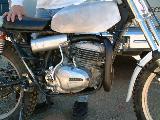
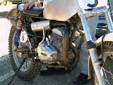
25, 27 and 28 show the bike with the system, prior to trying
it out.
29 and 30 show the bike at the event with the Miller absorption
silencer in place, and a bit of paint on the steel bits.
I hope you found this reasonably instructive and interesting.
I'll try and get all the above and some links into the new additions
section of my website later this week.
cheers,
Michael
Michael Moore
Euro Spares, San Francisco CA
Distributor of Lucas RITA and Powerbase products
Sole North American distributor of "The Racing Motorcycle: a technical guide for
constructors"
Host of 8 m/c email lists (details on the web site)
(((click here))) to go to EUROSPARES.COM
AFM/AHRMA #364